VeriSim - Development of measurement methods for propagation of pressure waves in fluid power piping systems
The advantage of hydraulic machines lies in their high power density and the decentralised energy distribution with the help of piping systems, which results in very compact and flexible technical solutions. So far, the piping systems have been treated mainly as pure energy transmission elements, and their signal transmission properties (intended and unintended sound propagation by the fluid) have been insufficiently and inconclusively researched.
Although simulation models have been considerably extended in recent years, the huge effort required for experimental validation has been omitted for economic reasons. On the other hand, there are pragmatic approaches in product development where different types of measurement methods are used to make a component pre-selection. However, in this case the measurement methods are questionable and the correspondence to the overall system is lacking.
The VeriSim project aims to close the remaining gap between novel simulation methods and their still missing experimental validation.
Motivation
In recent times, increasing energy efficiency with a simultaneous rise in comfort demands, e.g. in the area of acoustics, has become increasingly important. For example, a load-based energy supply can be realised via a speed-regulated drive, which, however, implies - in contrast to a fixed displacement pump - a broad spectrum of frequencies excited by the pump. Furthermore, energy-saving systems result in new system architectures, e.g. arrangement of electro-hydraulic motor pump units with very short piping systems close to the actuators.
However, the advantage of the free arrangement of the actuators is offset by the disadvantage of the system properties depending on the piping arrangements. In unfavourable cases, this can manifest itself in noise or vibrations, e.g. a piping system can be in resonance with a pump excitation.
The competitiveness of hydraulic systems thus increasingly depends on mastering the component "piping system" between energy generators and actuators.
Solution
To simulate the transmission behaviour of a hose line, information about the dynamic (visco-elastic) behaviour of the hose wall is required in addition to geometric parameters.
The geometric parameters such as inner and outer diameter or length can be determined from the hose specification. In order to determine the parameter values of the wall model, the resonances of the hose line are required depending on the free fabric length, i.e. the frequencies at which pressure oscillations at the inlet of the hose line leave it again at the other end with maximum amplification.
For this purpose, hoses of the same type but different lengths are examined by measurement on a test bench. Since the material properties of the hose depend on both pressure and temperature, the estimated parameter values are only valid for the operating point set during the measurement (T and p kept constant).
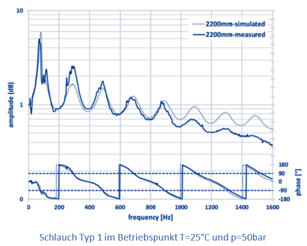
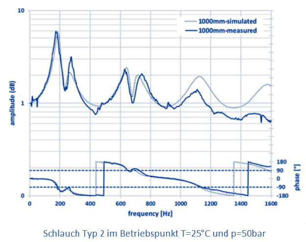
For verification, the fully parameterised model of the hose assembly is integrated into a simulation model which replicates the test bench. Subsequently, the test bench experiment is repeated by means of simulation. Finally, the transfer functions determined by measurement are compared with the respective transfer functions calculated from the simulation results (see adjacent figures of the transfer function T11 of the transmission matrix).


However, the user is typically not interested in the individual component model; rather, the models are to be used in the simulation of entire hydraulic (piping) systems. The aim is to calculate the system behaviour in advance, which means that a costly prototype of the corresponding system can be avoided.
In order to demonstrate the serviceability of the previously described methodology for this field of application, various configurations of pipe systems are simulated. The piping systems are composed, for example, of the adjusted models of hoses 1 and 2. For validation, the corresponding combination is measured on the system test bench.
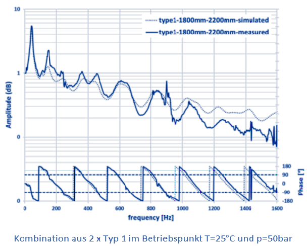
The adjacent figures show a comparison between the measurement and simulation of piping systems. The upper graph shows the transfer function T11 of a series connection of two hoses of the same type (type 1) but of different lengths. The frequency response is reproduced very well and the resonance frequencies are accurately matched. The amplitudes at resonance and extinction frequencies also correspond to those of the measurement.
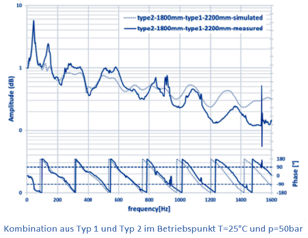
The lower graph shows the transfer function T11 of a series connection of two tubes of different types (type 1 and type 2). Again, the comparison between measurement and simulation shows a good general agreement.


