KonZwi - Efficiency increase of a constant pressure system through an intermediate pressure line
The research project "Increasing the efficiency of a constant pressure system using an intermediate pressure line - KonZwi" aimed to develop a new hydraulic set-up for the efficient operation of hydraulic cylinders in mobile machinery.
For the research project, a wheel loader was equipped with instrumentation and representative load profiles were measured. Based on these measurements, a control strategy was developed and programmed on a controller. A simulation model validated on the basis of the measurements was coupled with the code of the controller, the control algorithms were subsequently optimised and the projected energy savings were estimated through simulation.
The results of the simulative analysis show an energy saving potential of 13% in the hydraulic system, which, according to an initial estimate, would lead to an annual fuel saving of 5,846 litres of diesel fuel during operation (combination of drive hydraulics and working hydraulics).

Motivation
The KonZwi system consists of a constant pressure line (high pressure line), a tank line and an intermediate pressure line with a pressure level between the high pressure and tank pressure. A hydraulic accumulator is connected to the intermediate pressure line, which can store energy recuperated from the working hydraulics and release it again later. Due to the different pressures in the three lines, different pressure ranges can be provided individually for each consumer by means of switching valves. This leads to a reduction in throttling losses at the controlling proportional valves.
In order to minimise energy consumption, an overall control concept is required that takes over both the control of the cylinders and of the switching valves. For the adjustment of the speeds, the controller receives a desired speed signal from the operator via the joystick.
Before testing on the actual machine, the developed control algorithm is to be programmed on a mobile control unit and first validated in conjunction with a simulation model of the system.
Solution
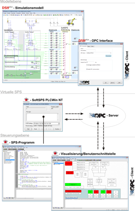
In the KonZwi project, the development and test phases of the control strategy were carried out in a time-saving manner by coupling the real CoDeSys PLC software to the virtual model in DSHplus. This procedure is also known as software-in-the-loop (SiL) and, together with the coupling of real hardware to virtual models (hardware-in-the-loop), represents the state of the art in control design.
This allowed the control program to be developed and tested in detail parallel to the modification of the real system. The PLC program developed and optimised in this way was then loaded directly onto the real PLC and could be evaluated on the basis of repeated measurements on the reference system.
The adjacent figure shows the coupling of the real control program and the virtual wheel loader model. The core of this simulation environment is a virtual PLC, the so-called SoftPLC, which emulates the real control system. Just as on the actual control hardware, an OPC server (Object Linking and Embedding for Process Control) is provided by the SoftPLC. Within this OPC server domain, all state variables of the control, such as pressures or valve control signals, are available as objects. Various OPC clients can be linked to this OPC server. The OPC clients have full access to the common OPC server and can write or read data of individual objects within this domain. In the actual controller these individual objects are linked, for example, with the memory locations of the sensor connections. In the case of the described coupling, state variables of the model are assigned to the individual objects. It is not obvious to the control program whether the individual objects are fed by data from the real system or by simulation results from the virtual model.
In order to be able to calibrate the input and output signals on the basis of the virtual model in advance, the electronics of the sensors and actuators were also mapped within the simulation model so that the model signals with the corresponding electrical units, current and voltage, can be exchanged with the control system.
Keywords: hydraulics, hybrid, intermediate pressure line, software in the loop, control strategy