

Virtual Commissioning

Virtual commissioning represents a part or starting point of a future product lifecycle management supported entirely by digital twin methodology.
“The digital twin is disrupting the entire Product Lifecycle Management (PLM), from manufacturing to service and operations. Nowadays, PLM is very time consuming in terms of efficiency, manufacturing, intelligence, service phases and sustainability in product design. A digital twin can merge the product physical and virtual space. The digital twin enables companies to have a digital footprint of all of their products, from design to development and throughout the entire product life cycle.” (quote from wikipedia)
Advantages at a Glance
- Results in time saving
- Supports interdisciplinary work
- Leads to detailed internal product documentation
- Generates an extensive internal knowledge base
- Enables Software development and testing in the Software-in-the-Loop (SIL) environment
- Validation takes place on real PLC in the Hardware-in-the-Loop environment (HIL)
- Allows user or customer testing and feedback based on the virtual prototype
- Identifies design problems much earlier
- Enables more cost-effective corrective action
- Leads to a better quality of the product design
Benefits of Virtual Commissioning in Detail
Virtual commissioning is based on the digital twin of a technical system or subsystem combining the different relevant technical domains like mechanics, hydraulics, electronics and software. But let us first look at the “Why?”. What are the goals and benefits of Virtual Commissioning?
One of the most important and obvious benefits is the gain in time compared to the classic process, visualized in the following figure:
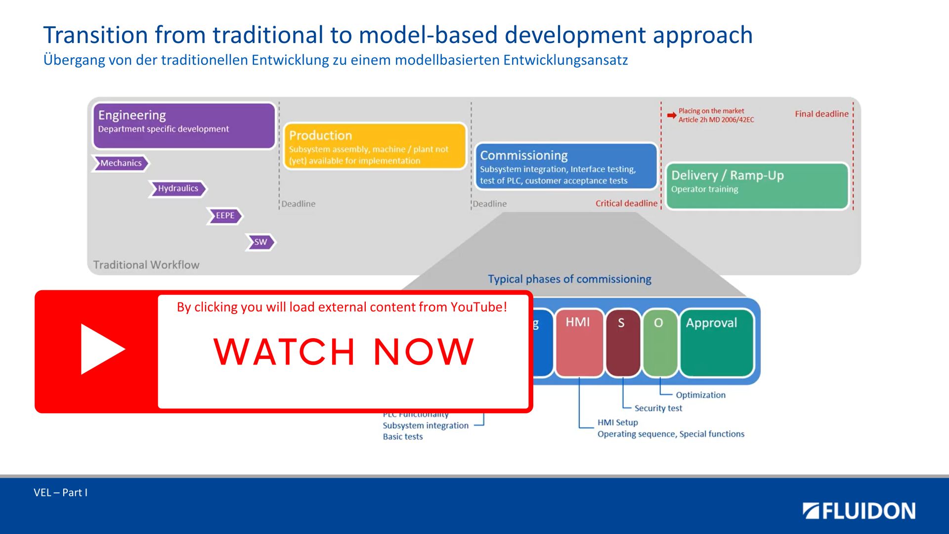
A major part of the integration and commissioning work can be done even before a physical prototype of the machine exists.
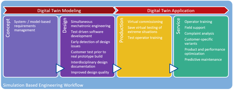
However, benefits of virtual commissioning go far beyond this aspect. As the above figure also shows, each engineering discipline, like mechanical, electrical and software engineering contributes to the Digital Twin, thus interdisciplinary work and communication are promoted at an early stage of product development. The resulting Digital Twin represents an excellent internal product documentation and knowledge base.
Virtual commissioning offers great benefit especially for the electronics and software engineers: While in the classic process, software development and testing often can only be done on the real prototype, now software is developed and tested in the software-in-the-loop (SIL) environment with the virtual prototype as a first step of integration. After selection of the appropriate hardware, even the software is tested on the real PLC in the hardware-in-the-loop environment. The human-machine-interface (HMI), consisting of components such as joysticks, control panels and displays, can already be part of this test setup, not only enabling a test from an engineering point of view but also user or customer testing and feedback based on the virtual prototype. Extreme situations of the machine can be tested at this stage without any risk.
This early integration also reveals design issues much earlier than the traditional process, thus allows for more cost-effective corrective action than at a later stage and leads to better product design quality.
Virtual Prototyping - The First Steps to the Digital Twin
The virtual prototype represents the core of the virtual commissioning process. Build and refinement of this prototype shall be a major part of the design work. Even though every engineering discipline is setting up “its” model, it requires interdisciplinary work to define and setup the interfaces between the different submodels. Design issues due to the lack of communication are therefore minimized. This process also forces to specify and document all components at an adequate level, improving design documentation quality. Impacts of design changes get visible for the entire design team.
The following workflow is an example of virtual commissioning. The steps shown are executed in parallel, typically in several loops, starting with the "rough" modelling and ending with a refined virtual representation of the machine with sufficient accuracy.
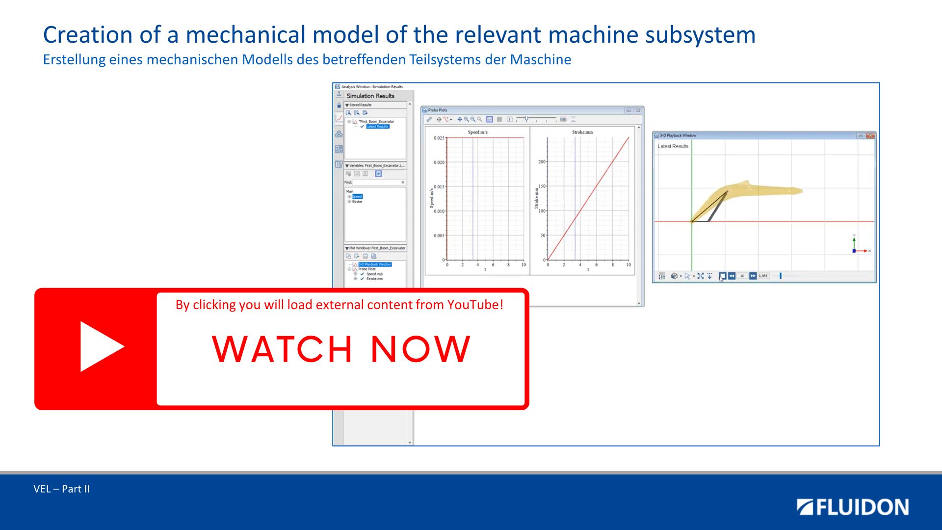
Creation of a Mechanical Model of the Relevant Machine Subsystem
On the basis of
- 3D CAD data
- Material data
- Data of the components
a kinematic model of the machine and / or subsystem is created.
The interfaces to the "neighbouring" domains, e.g. to hydraulics, are taken into account accordingly during the model design.
After the successful model test, the mechanical model is exported as an FMU and is available for coupling with FMUs from other domains.
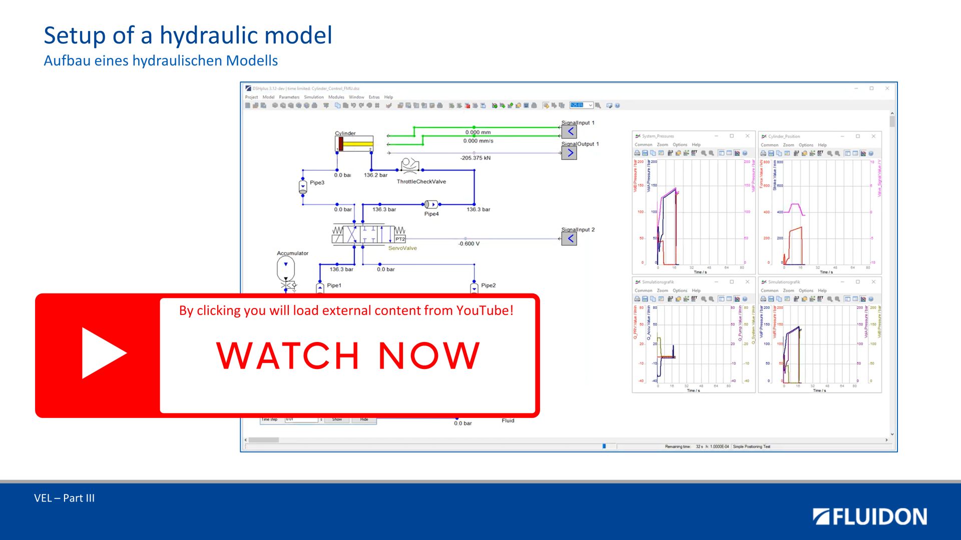
Setup of a Hydraulic Model
A similar approach to the modelling of the mechanics is used for the hydraulics. Information for modelling the hydraulics can be obtained from
- Circuit diagrams
- Parts lists
- Component data from suppliers
(e.g. description of the dynmaic valve behaviour).
The hydraulic model is also exported as an FMU after completion.
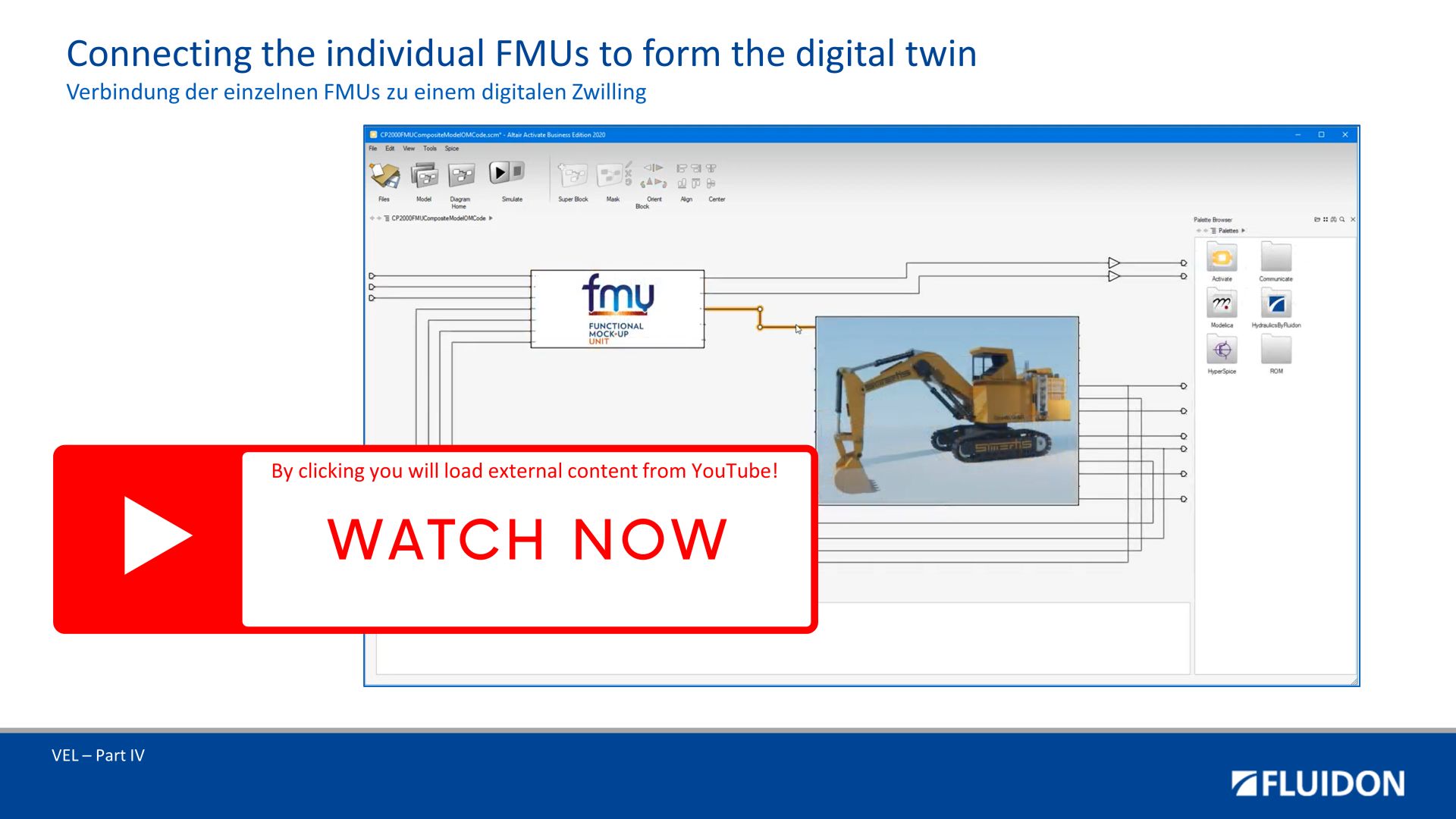
Connecting the Individual FMUs To Form the Digital Twin
Once the individual, domain-specific models have been created and exported as FMUs, they can now be combined to form the digital twin of the machine or the relevant machine subsystem.
In doing so, the sub-models only need to be connected at the previously defined interfaces.
The result is the so-called composite FMU.
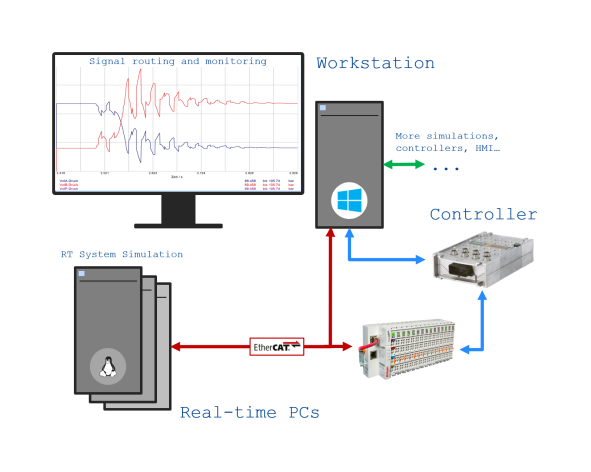
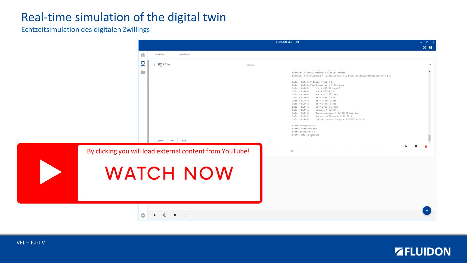
Real-Time Simulation of the Digital Twin
A real-time calculation job is created in the VEL Orchestrator that contains the composite FMU (digital twin). This calculation job is executed on the VEL Real-time Simulator.
In addition to the calculation job, a 3D visualisation and live scopes can also be created.
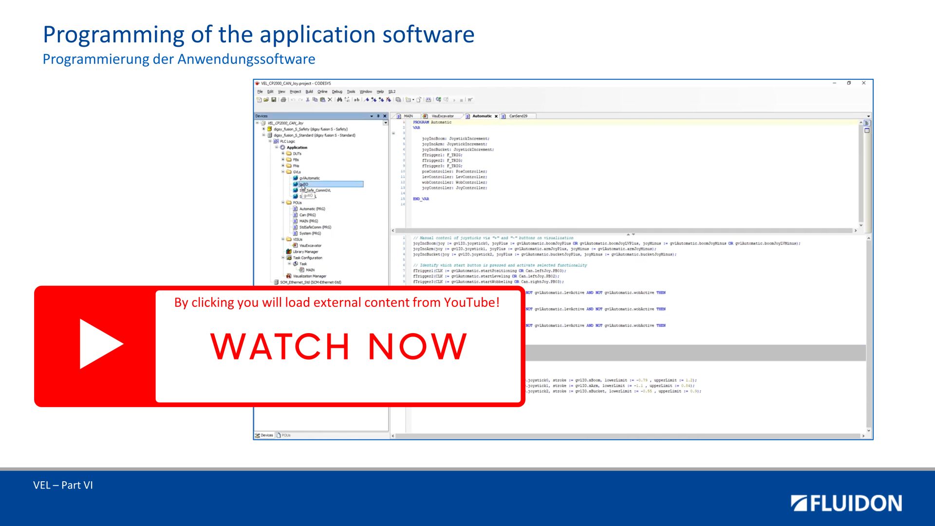
Programming of the Application Software
Parallel to the modelling of the digital twin, the application software can be programmed.
During virtual commissioning, the software can be tested against the digital twin.
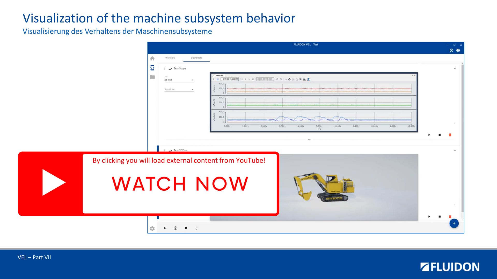
Visualisation of the Machine / Subsystem Behaviour
With the help of virtual commissioning, the developed machine functions can be checked. It is helpful to visualise the relevant variables.
The VEL offers the possibility of visualising process data in 2D, but also displays the movement behaviour of complete machines in 3D.
This example workflow for virtual commissioning shows that a large part of the work of the classic development process now becomes part of model-based working: Software development, testing and improvement up to the presetting of most parameters is done during virtual prototyping.

