Piping System Library – 1D-CFD: Efficient Simulation of Hydraulic Systems
Designing and ensuring the safe operation of hydraulic piping systems confronts engineers with complex challenges. With our extensive experience and proven solutions, we are a leader in the niche of 1D-CFD simulation – an area in which most of our service projects and the most important software customers are to be found.
Why 1D-CFD?
While 3D-CFD simulation requires complex and computationally intensive models, 1D-simulation is convincing due to its numerical efficiency. It enables the analysis of unsteady changes in the operating state of a hydraulic piping system in a single simulation run. This saves time and money without compromising on accuracy. 1D-CFD technology is particularly suitable for:
- Analyzing vibrations and pressure surges in pipelines
- Testing pipeline networks in oil and gas facilities
- Optimizing water distribution systems and heating systems
- Applying vehicle hydraulics, for example in passenger cars and commercial vehicles
What all these systems have in common is that the transported medium is under pressure. This makes precise analyses essential to avoid problems during operation. Especially in the case of large, branched piping networks, the interaction of the components and the piping network must be critically analyzed as early as the planning phase.
Our Strength: Specialization in Dynamic Piping Systems Using 1D-CFD
Most of our service projects and software applications focus on the dynamic analysis of piping systems. In contrast to 0D-simulation, which focuses on the interaction of components such as pumps, valves and cylinders, 1D-CFD simulation enables the targeted investigation of vibrations and pressure surges in pipelines – a crucial factor for safe and efficient system planning.
Library Features
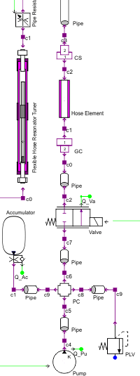
Our piping system library covers a wide range of tasks:
- Standard model: standard analysis of hydraulic and pneumatic circuits
- Viscoelastic properties: consideration of damping properties in hoses and plastic pipes
- Thermal hydraulics: consideration of heat transfer and heating
- Fluid-structure interaction: dynamic properties of the pipe wall (bending, torsion, longitudinal section)
- Cavitation: simulation of vapor and gas cavitation
- Gas transport: transport of undissolved gas within liquids
Put your trust in our expertise in the niche of 1D-CFD simulation.

Fields of Application for 1D-CFD
With our in-depth knowledge and powerful DSHplus software, we are your partner for reliable simulations in piping design. Our specialization in this area ensures that your systems can be designed safely and efficiently.
Learn more about the advantages of 1D-CFD simulation for your project. Contact us now.
